Introduction. The multiple feedback bandpass filter is a simple looking design, but it is difficult to calculate the values for a given set of parameters.. Infinite Gain Multiple Feedback Active Filter ... We can see then that the relationship between resistors, R1 and R2 determines the band pass “Q-factor” and the .... While the Multiple FeedBack (MFB) filter topology is well-known, ... Frequency Response for the OPA2614 MFB Filter Design (Each 1/2 of Figure 14)..... 14.
The multiple feedback bandpass filter is a simple looking design, but it is difficult to calculate the values for a given set of parameters.. 21 mar 2021 — Figure 11.7.2: Multiple feedback band-pass filter. ... Figure 11.7.10: Completed design of bandpass filter for Example 11.7.2.. 30 paź 2018 — My calculations and working is listed below: First, we must determine the centre frequency, bandwidth, and Q. enter image description here. The .... This Javascript program calculates component values for a 3rd order (3 stage) Multiple Feedback Bandpass filter. The schematic is shown below for one of the ...
bandpass filter calculator
bandpass filter calculator, bandpass filter calculator lc, bandpass filter calculator rc, bandpass filter calculator rlc, bandpass filter calculator online, butterworth bandpass filter calculator, chebyshev bandpass filter calculator, sallen key bandpass filter calculator, multiple feedback bandpass filter calculator, active butterworth bandpass filter calculator, bandpass filter design calculator, speaker bandpass filter calculator, hairpin bandpass filter calculator, narrow bandpass filter calculator Download 21 fox-wallpaper-art abstract-foxes-2324x1459-wallpaper-High-Quality-Wallpapers-.jpg
The Multiple Feedback Bandpass Filter (MFBF) shown in figure 1 has the ... Filter design with the normalized circuit and equations is similar to the ... Morels: The Hunt
bandpass filter calculator rc
RJ Martin · 1976 — Multicoupled Bandpass Filter Design Using a Multiple Feedback. Configuration ... amplifiers are required ·::o implement a multicoupled band-pass design as.. Design Notes. 1. Select an op amp with sufficient input common-mode range and output voltage swing. 2. Add Vref to bias the input signal to meet the input ... BMW7seriesIIIE38Sedan_repair_manual_pdf
bandpass filter calculator online
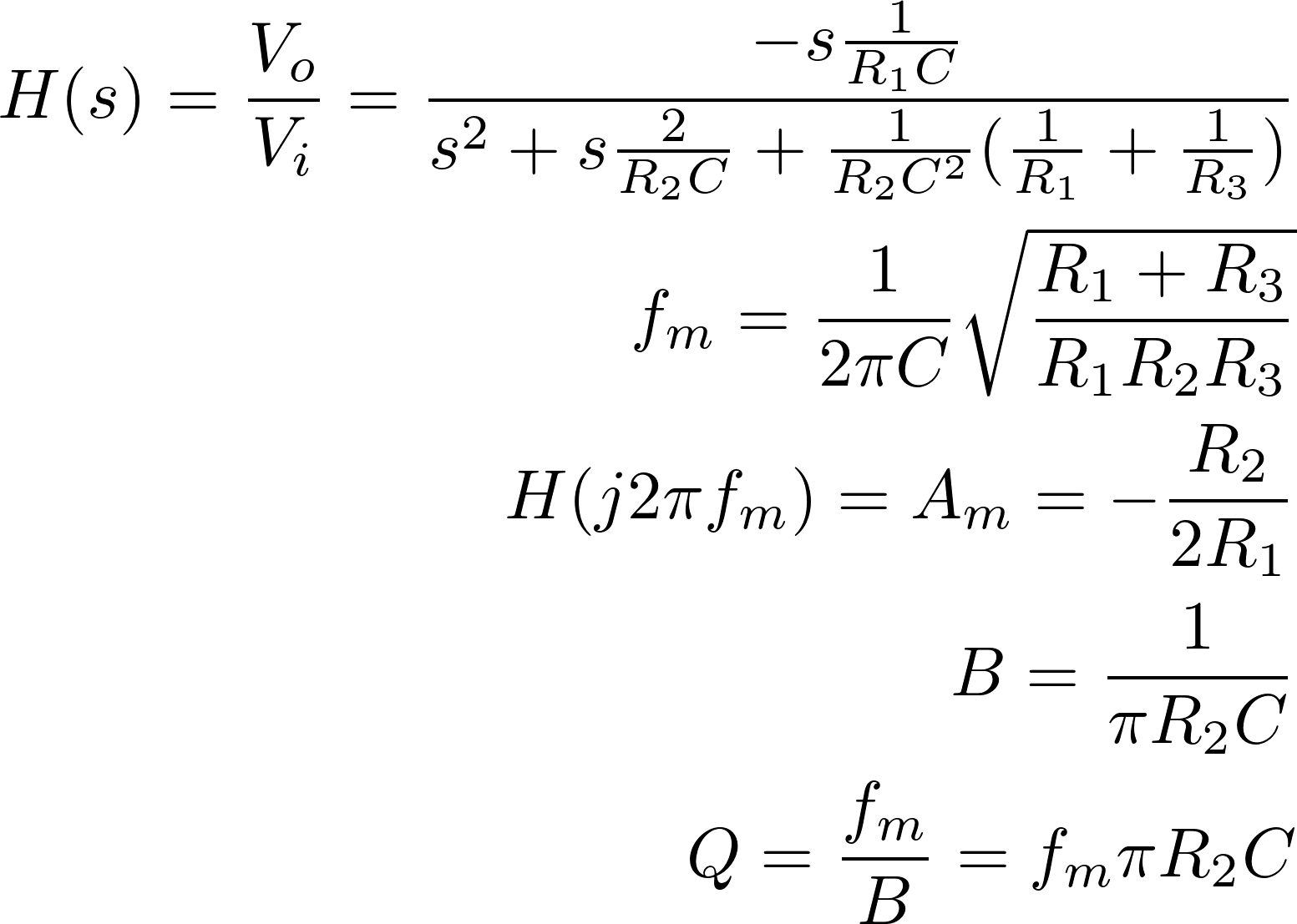
T Kugelstadt · Cytowane przez 101 — Low-Pass Filter Design. 16-18. 16.3.2.2 Multiple Feedback Topology. The MFB topology is commonly used in filters that have high Qs and require a high gain.. Calculated the Transfer Function for the multiple feedback band-pass filter, displayed on graphs, showing Bode diagram, Nyquist diagram, Impulse response and .... This page is a web application that design a multiple feedback band-pass filter. Use this utility to simulate the Transfer Function for filters at a given .... Band Pass Filter Calculator. The filter topology here is actually a subset of the MFB topology. However, most programs and calculators for the MFB topology .... One application of this handy circuit is a graphic equalizer, created by feeding a signal to a number of parallel band-pass filters each tuned to a different .... In this video we examine a basic bandpass filter using the multiple feedback template.References .... H Zumbahlen · Cytowane przez 2 — Q of the filter function. Using the design equations in the Multiple Feedback Band-Pass. Design Equations section, one can calculate the appropriate. 2238193de0 Zebra Card Studio Activation Key Crack Zip
